Last update: April 7, 2025
This page covers my planning, development and building of a Wireless ESP32 FlatPanel for my SkyWatcher 150PDS telescope.
The plan#
Found an existing project that makes a wireless FlatPanel, however uses a custom ASCOM driver, where I want to use the native Alpaca protocol to directly integrate with ASCOM devices and is cross-platform. https://github.com/jlecomte/ascom-wireless-flat-panel
My Requirements#
- Wireless communication directly with ASCOM/Alpaca over wifi
- Powered with 5V 2-3A, ideally from battery
- 3D print for housing, mounting etc.
- Diffuser, reflector and light-guiding panel for flat light.
The Plan#
- Use an ESP32 with Alpaca
- Try to make my own Light Guiding Panel (LGP) with laser cutter, although if it fails, buy a cheap lamp and use its LGP
- Use DotStar LED-strip, as it has built-in PWM driver and resistor for each LED (And gives more control over light temperature)
Building it#
Here I cover the process, results and learning points of the actual build.
ESP32 Firmware#
I spent two nights on building the initial firmware, writing it in c++ with Arduino libraries. It is made to automatically join a known network as I tend to use it either with a hotspot or the home wifi.
After a night or two more fixing bugs the firmware now passes the ASCOM ConformU test and is thus confirmed to follow the alpaca standard.
The firmware: https://github.com/Crowdedlight/EspFlatPanel
The LEDs
The LEDs are set to output “Neutral White” which corresponds to RGB(252,250,246).
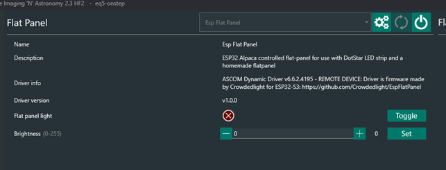
Connecting to it the first time#
As it implements the Alpaca protocol, you have to use the ASCOM tools to auto-discover it and add it to known devices the first time. This “installs it” so it will show up as a ASCOM device in NINA etc.
To do this:
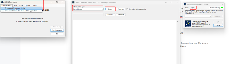
- Open “ASCOM Diagnostic”
- Select “Choose Device” and then click “Choose and connect to device”
- Select “CoverCalibrator” in the dropdown menu and click on “choose”
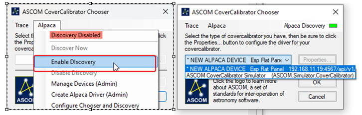
- Click on the Alpaca menu and select “enable discovery”
- The ESP32 will then be found if on the same wifi network
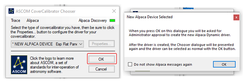
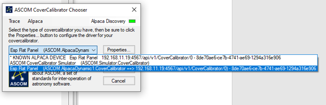
- Selecting the ESP32 device you can add it as “dynamic driver” so it will appear as ASCOM device whenever it is connected to the same wifi network
Video of controlling the LEDs through NINA:
Making the Panel#
After reading multiple sources and projects on how to structure it to give a flat uniform light, the following layers was chosen. From bottom and up, with up being what is connected to telescope.
- Bottom-plate/housing
- Reflective film/layer
- LGP (LEDs sit tightly wedged around the edge, shining into the edge all around)
- Internal Diffuser (2-3mm white acrylic)
- Spacer (3D Print)
- External Diffuser (2mm white or opaque acrylic)
In the case 2 diffusers gets too much, one can be replaced with a spacer. The housing is made from 3D print based on
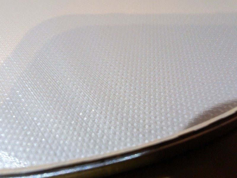
Light Guiding Plate (LGP)#
I spent a good while trying to google how to make these yourself with a laser-cutter, or if possible to buy one premade to specific diameters, but I did not find anything that was feasible, as its a product that is mostly sold in wholesale at high volume in Business to Business.
I did however find this hackaday project: https://hackaday.com/2023/03/13/a-hackers-introduction-to-diy-light-guide-plates/ which describes part of the process on how to make a LGP. Essentially its based on etching small holes in patterns across an acrylic plate.
I also found out that the lasercutter program RDWorksV8 has a LGP feature that should be able to generate patterns for LGPs. I tried to do a couple of versions on the models in https://github.com/jlecomte/ascom-wireless-flat-panel although modified for my own size and electronics. The files are available at: https://github.com/Crowdedlight/EspFlatPanel/tree/main/3d_print

As the image shows, the self-made LGP does not really work. It gets more light into the middle, but it does not distribute the light in a uniform matter, that is important so it becomes “flat”.
Commercial lamps to the rescue
So I opted for the backup plan, buy a cheap ceiling lamp, with the approx diameter I need, and designed to provide a flat uniform light. Then disassemble it to get its LGP, reflector and diffuser.
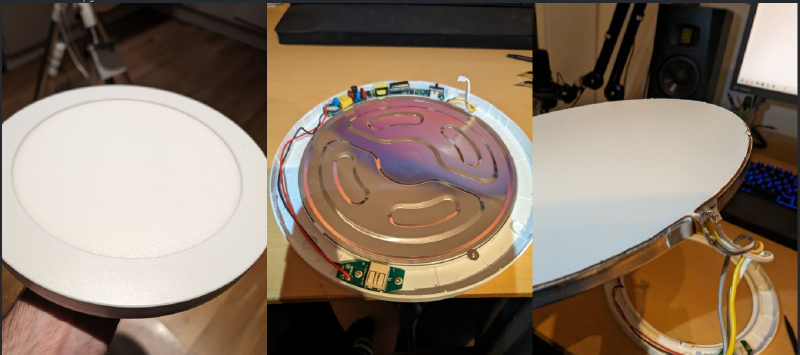
The LGP is seen below here
This resulted in a layer order of:
- Backplate (3D print housing)
- Bought reflector
- Bought LGP
- Lasercut Diffuser in opaque acrylic
- spacer
- Bought Diffuser
Which turned out like this:
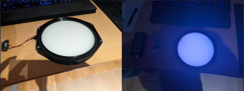
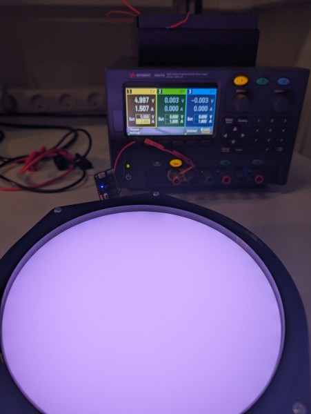
Which looks much better, although hard to capture properly on the phone. It ended up being 59 LEDs that at full brightness draws 1.5A.
Powering the LEDs and ESP32#
The LEDs used is the RGB LEDs APA102 with 60 LED/m. For the built panel 59 LEDs was used and during a test with powersupply they appeared to draw 1.5A at full brightness.
The initial plan was to use a power-bank that can provide 3A with USB to the ESP32, and then use the 5V pin on the ESP32 to power the LEDs. However that did not work out as after some tests the ESP32 got burnt.
My assumption is that the USB-in was not directly connected to the 5V pin, but ran though a 5V regulator, that was rated for much less current.
PCB to the rescue
So to solve this problem I decided to make my own PCB that could use a 1S2P Li-Ion battery and output 5V 3A, with included battery system for charging and safety.
I got a 1S2P Li-Ion battery with built-in battery protection circuit. That gives me a 3.7V with around 5A discharge. Plenty of current, but I need to boost the voltage to 5V, to run my LEDs and ESP32.
Initially I ordered a “china” 18650 PCB that could do it, but when I received it, the way it functioned would not work for my usecase as it would turn off after 10s and the quality was questionable.
So I decided to design a PCB myself, was also a good excuse to get better at Kicad and PCB designs! I selected some well-documented IC’s from Texas Instruments (TI) for the battery charging and boost switching regulator. The big benefit with TI IC’s is their quality datasheets that makes it easy to follow and figure out how to connect and trace it.
Originally I designed it with both an 5V and 3.3V output, as I could see it being useful for other hobby projects (and I have to order 5 at a time), but I ended up cutting it to save money and just stick with the 5V output.
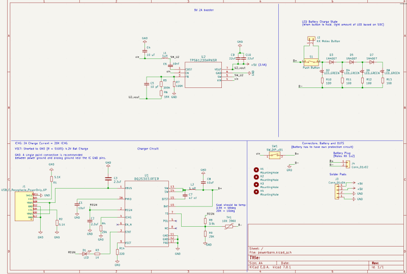
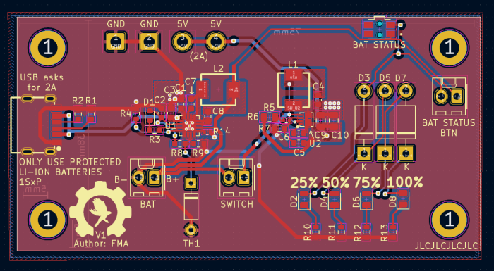
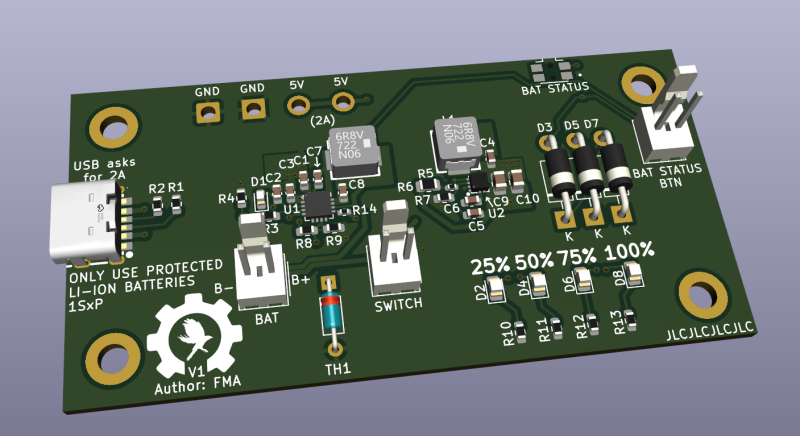
I ended up also adding connectors for a button, on/off switch and 4 LEDs on the board. To make it easy to turn it on/off with a switch, and use a push-button to light up the 4 LEDs based on how much charge is left in the battery. So a rudimentary battery-level indicator to check the charge left on the battery.
As I was ordering PCBs anyway i decided to make a breakout board for the ESP32 I was going to use, to have an easier time to mount it.
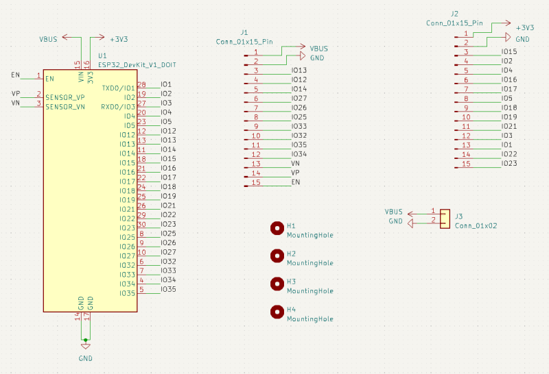

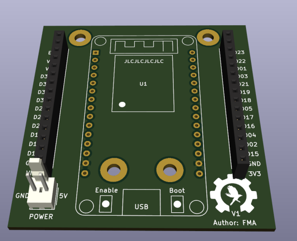
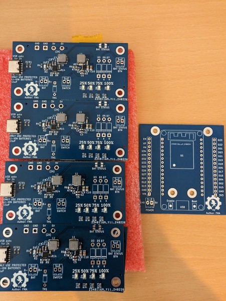
I ordered it all from JLC PCB, a chinese board manufacturer I have used before. Great for hobby projects as they are cheap and if using standard components they got on stock, even getting them to assemble and solder the components for you, is fairly cheap. They do manufacturer a minimum of 5 at a time, so I ended up with 4 spares of each.
To save money some of the through-hole components like the thermistor for battery-charging I had already and did not get assembled, but soldered myself.
It ended up costing about 500-550dkk including shipping for 5x power-board with components, and 5x ESP breakout boards without components (Had the sockets and connector already). Using the cheap shipping of $3 and 11-15 workdays, but it turned up already after 5 workdays, which was a pleasant surprise.
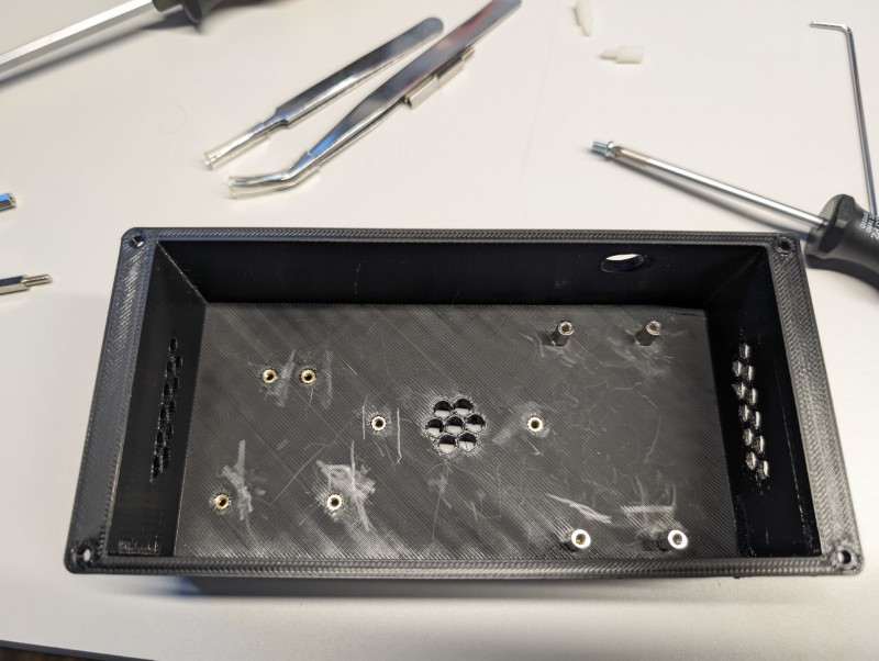
Assembling everything#
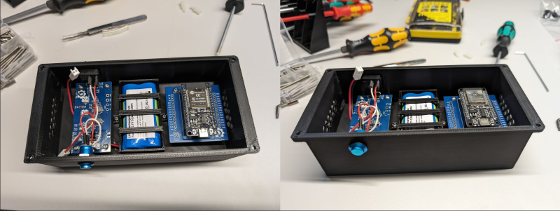
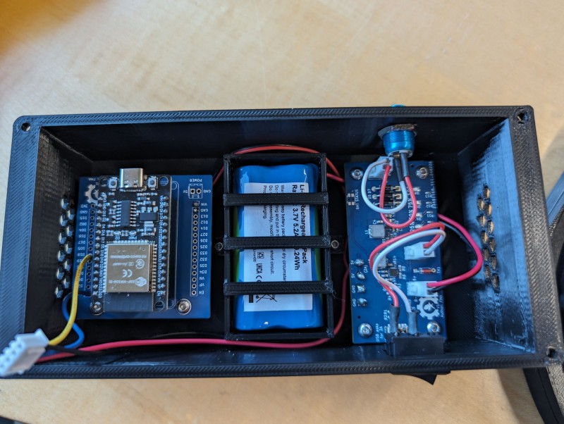
With the eletronics and the panel built it was time to assemble everything into the 3D printed parts. The parts used heat-inserts to add threading to the holes in the 3D print.
With ESP32, Battery-pack and Powerboard assembled
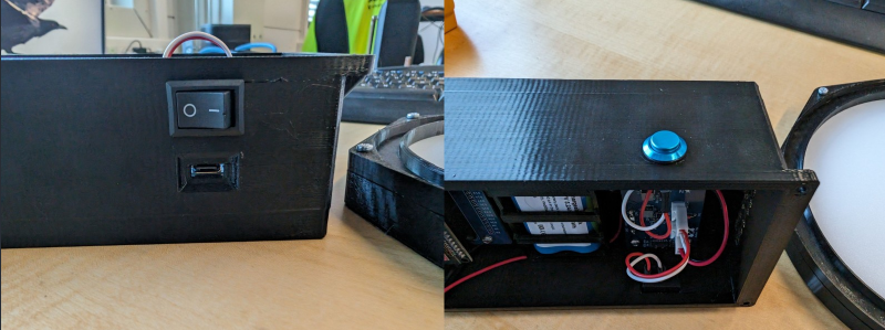
The on/off switch, USB-C charger plug and battery-check button installed into the 3D print
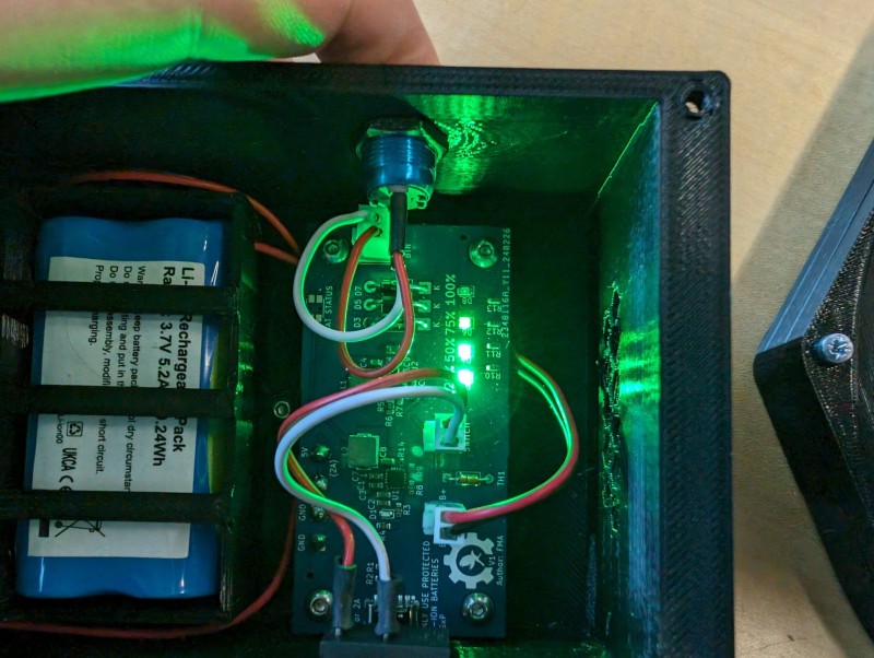
Pressing the button lights up the LEDs based on battery level. In hindsight those LEDs should probably have been connected with a connector so they could be moved out and placed in the 3D print, but made some holes in the 3D print instead to allow airflow and to see the lights instead.
Everything connected and tested with wireless control through NINA
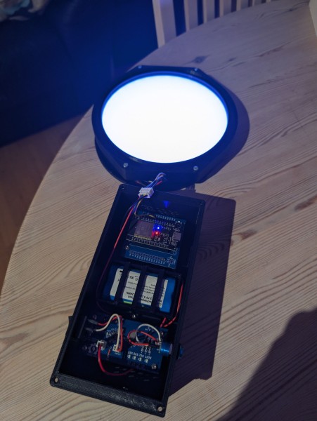
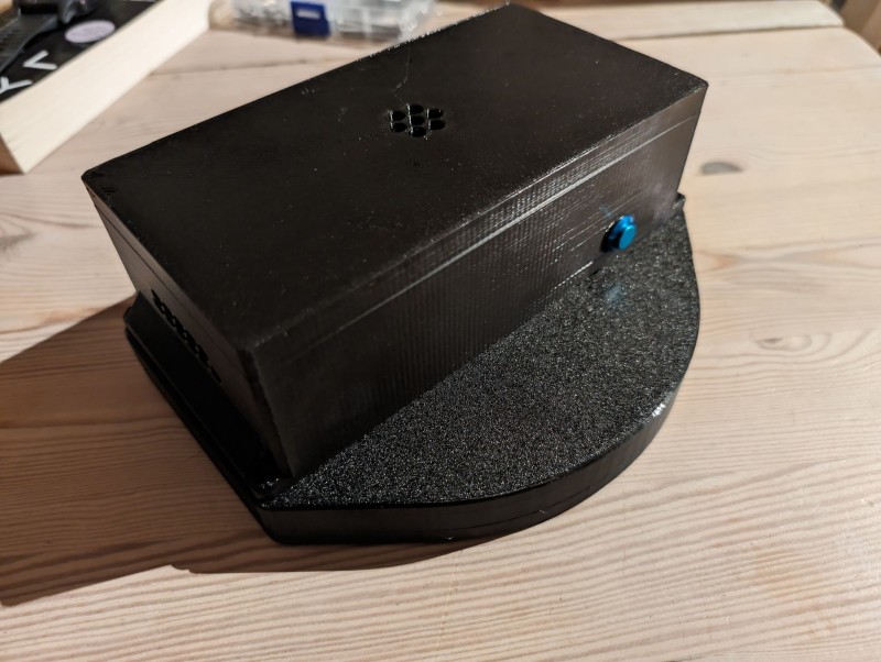
The combined box got a little bit bigger than expected, but still sits fine on the telescope and does the job perfectly. After having used it for multiple nights and sessions over the past months I have been surprised about how little the battery is used. But granted it is not turned on for that long duration at a time.
The RGB LEDs chosen are nice and easy to use as they come with own driver/resistor, but in hindsight they are overkill. I could probably have gone with some only able to output “Neutral White” at less brightness, and not had the same challenges supplying them with power.
But all in all a fun project that turned out very well, and works as it should, making it a breeze to take flats!